Ultrasonic inspection is widely used to verify weld integrity before parts enter service, and understanding how ultrasonic testing detects cracks is essential for preventing hidden structural failures.
Ultrasonic testing sends high-frequency sound waves into the material; when these waves encounter a discontinuity such as a crack, lack of fusion, or slag inclusion, part of the signal reflects back to the probe.
The timing and strength of that reflected signal reveal the flaw’s location, depth, and approximate size. In real fabrication and field inspection, this matters because surface-clean welds can still contain internal defects that lead to fatigue failure, leak paths, or rejected code work.
Correct probe angle, frequency choice, and calibration directly affect detection reliability and inspection cost. The explanation below clarifies the signal behavior, scanning methods, and interpretation principles inspectors use to reliably identify cracks inside welded joints before they become service problems.

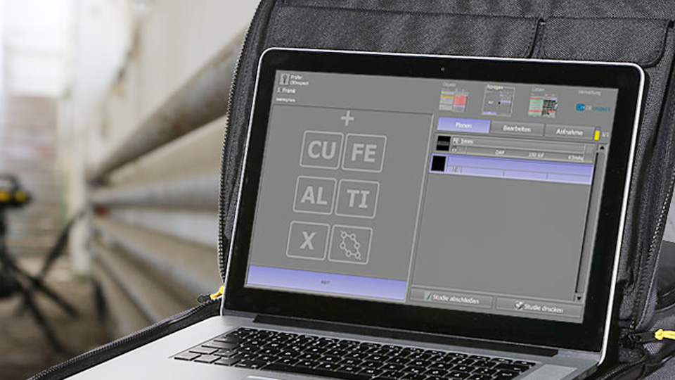
Image by fractory.com
Fundamentals of Ultrasonic Wave Propagation in Welds
Ultrasonic testing relies on the propagation of mechanical vibrations through the weld material at frequencies typically ranging from 1 MHz to 10 MHz, far exceeding audible sound.
These waves travel at material-specific velocities, with longitudinal waves moving at approximately 5,900 m/s in steel and shear waves at around 3,200 m/s.
The choice of frequency balances penetration depth and resolution: lower frequencies (e.g., 2 MHz) suit thicker sections up to 100 mm, while higher ones (e.g., 5 MHz) provide finer detail for shallow defects.
When introduced via a transducer, the waves encounter acoustic impedance mismatches at boundaries or discontinuities. Impedance, calculated as density multiplied by velocity, differs significantly between steel (about 45 MRayl) and air-filled cracks (near zero), causing near-total reflection.
This reflection coefficient approaches 100% for planar cracks perpendicular to the beam, enabling precise detection.
Longitudinal and Shear Waves
Longitudinal waves, also termed compression waves, involve particle oscillation parallel to the propagation direction. They penetrate solids, liquids, and gases efficiently, making them suitable for initial thickness measurements and detecting volumetric defects.
In weld inspection, straight-beam transducers emit these waves at normal incidence to scan for laminations in the heat-affected zone (HAZ).
Shear waves, with transverse particle motion, propagate only in solids and exhibit higher sensitivity to planar discontinuities like cracks. Generated through mode conversion at interfaces, they are refracted at angles (e.g., 45° or 60°) using wedges to optimize interaction with weld geometries.
For crack detection, shear waves “zigzag” through the material thickness, reflecting from internal or external anomalies based on time-of-flight differences.
Reflection and Diffraction Principles
Reflection occurs when waves strike a discontinuity larger than the wavelength, following the law of reflection where the angle of incidence equals the angle of reflection.
For cracks, the echo amplitude correlates with defect size and orientation: a 2 mm crack at 90° to the beam yields a strong signal, while tilted cracks reduce amplitude by up to 20 dB.
Diffraction supplements reflection for edge detection, as waves bend around crack tips, producing low-amplitude signals independent of orientation.
This is crucial for sizing, with time-of-flight measurements providing depth accuracy within ±0.5 mm in calibrated setups. In practice, combining both principles ensures comprehensive flaw characterization.
Equipment and Transducer Configurations
Ultrasonic testing equipment includes a pulser-receiver unit, transducers, and display systems like A-scan for time-amplitude graphs, B-scan for cross-sectional views, or C-scan for planar mapping. Piezoelectric crystals in transducers convert electrical pulses into vibrations and vice versa, with damping materials controlling pulse duration for resolution.
For weld cracks, probe diameters range from 10 mm to 25 mm, influencing beam spread: smaller probes focus energy for better near-surface detection but limit penetration.
Advanced units like phased array systems use multi-element arrays (16-128 elements) for electronic beam steering, covering angles from 30° to 70° without mechanical adjustment.
Straight Beam and Angle Beam Probes
Straight beam probes operate in pulse-echo mode, sending longitudinal waves perpendicular to the surface. They detect root cracks by measuring back-wall echoes interrupted by defects, with signal loss indicating flaw presence. Calibration uses reference blocks with flat-bottom holes (FBH) sized at 1.5 mm diameter for sensitivity setting.
Angle beam probes, mounted on wedges (e.g., Perspex with 35°-70° refraction), produce shear waves for oblique incidence. A 60° probe suits 30° bevel welds, ensuring 90° impact on sidewalls for maximum reflection from fusion lacks or cracks. Full-skip scanning covers the entire weld volume by reflecting off the back wall.
Couplants and Calibration
Couplants like gels or oils eliminate air gaps, matching acoustic impedances for efficient transmission (transmission coefficient >90% with proper viscosity). Water immersion is used for automated systems.
Calibration involves velocity determination (e.g., using IIW blocks for steel at 3,240 m/s shear) and sensitivity adjustment via distance-amplitude correction (DAC) curves, compensating for beam attenuation over depth. Reference reflectors like 3 mm side-drilled holes set the 80% full-screen height threshold for defect evaluation.
Detection Mechanisms for Common Weld Cracks
Weld cracks vary by location and orientation, requiring tailored scanning patterns. Root cracks, often from incomplete penetration, are detected via high-amplitude echoes in half-skip mode using high-angle probes (70°), with diffraction from tips aiding sizing to ±1 mm accuracy.
Side wall cracks in the HAZ appear as clustered signals in full-skip scans, with shear waves reflecting strongly if aligned perpendicularly. For misoriented cracks, amplitude drops necessitate multi-angle sweeps.
Root Cracks
These surface-breaking defects from the weld root disrupt longitudinal wave paths in straight-beam testing, causing early echoes. In angle-beam mode, they trap back-wall signals, with time-of-flight indicating depth from 0.5 mm to full thickness.
Practical insight: In shop environments with thick plates (>50 mm), lower frequencies (2 MHz) reduce attenuation for reliable root detection.
Side Wall Cracks
Internal cracks along prep faces reflect shear waves at 45° incidence, producing overlapping signals for branched defects. Phased array enhances detection by focusing beams, revealing crack height via tip diffractions.
Toe Cracks
Surface-breaking at the weld cap edge, toe cracks are scanned with high-angle probes in half-skip, showing strong near-surface echoes. Full-skip confirms extension into the base metal.
Center Line Cracks
Embedded or surface-breaking in multi-pass welds, these are detected via diffraction in TOFD setups, with lateral wave interruptions signaling presence. Sizing uses hyperbolic cursors on B-scans for length and depth.
| Crack Type | Typical Location | Detection Wave Type | Key Signal Characteristic | Sizing Accuracy |
|---|---|---|---|---|
| Root | Weld root/ID | Shear (high angle) | Back-wall trap, tip diffraction | ±0.5 mm |
| Side Wall | HAZ/prep face | Shear (45°-60°) | Clustered reflections | ±1 mm |
| Toe | Weld toe/cap | Shear (half-skip) | Near-surface echo | ±0.5 mm |
| Center Line | Weld center | Longitudinal/Shear | Diffraction patterns | ±1 mm |
Advanced Ultrasonic Techniques for Enhanced Crack Detection
Conventional methods suffice for standard inspections, but advanced techniques offer superior resolution for complex welds.
Phased Array Ultrasonic Testing (PAUT)
PAUT uses array transducers to steer and focus beams electronically, covering 30°-70° sweeps. It detects all crack types via sectorial scans, with imaging displaying defect orientation. Advantages include reduced scan time by 50% and better sizing through focal laws.
Time of Flight Diffraction (TOFD)
TOFD employs dual probes for diffraction measurement, independent of amplitude. It excels in center line cracks, sizing via time differences with 0.1 mm resolution in 20-50 mm thicknesses. Setup uses 5-10 MHz probes separated by 2x thickness.
Total Focusing Method (TFM)
TFM processes full matrix capture data for pixel-focused images, using modes like TT (transmit-transmit) for direct reflections or TTT for skips. It provides high-fidelity views of side wall cracks, combining modes in TFMi for shape detail. Resolution reaches 0.2 mm for embedded defects.
Signal Interpretation and Sizing of Cracks
A-scan displays show initial pulse, defect echoes, and back-wall signals. Crack signals appear as sharp peaks with amplitudes >20 dB above noise, located by velocity-time calculation (e.g., 10 μs round-trip at 3,200 m/s yields 16 mm depth). Sizing uses 6 dB drop method for length or tip diffraction for height, with B-scans aiding visualization.
In welds, false calls from geometry (e.g., root reinforcement) require pattern recognition: cracks show faceted, multi-peak signals versus smooth porosity echoes.
Practical insight: For austenitic stainless welds, use longitudinal waves at 45° to mitigate grain scattering, improving signal-to-noise by 10-15 dB.
Practical Applications and Limitations in Welding Inspection
Ultrasonic testing applies to ferrous and nonferrous welds from 8 mm thickness, detecting cracks in pipelines, boilers, and bridges per AWS D1.1 codes. It outperforms radiography for planar defects, locating with one-side access.
Limitations include orientation dependency (tilted cracks <30° may miss detection), surface roughness requiring preparation, and operator skill for interpretation. High temperatures (>150°C) demand special probes, and coarse-grained materials attenuate signals by 20-30 dB/m.
Practical insight: In field repairs, portable phased array units reduce setup time from hours to minutes, enhancing efficiency for U.S. technicians.
Wrapping Up
Ultrasonic testing delivers robust crack detection through precise wave interactions, enabling quantitative assessment critical for weld quality. Its integration of conventional and advanced methods ensures comprehensive coverage, from root to cap.
For optimal results in high-stakes applications, leverage hybrid approaches like PAUT with TOFD to cross-verify sizing, minimizing rejection errors.
In fatigue-prone welds, monitor crack growth rates via periodic UT, correlating amplitude increases with propagation models to predict remaining service life accurately.
FAQs
What frequencies are typically used in ultrasonic testing for weld cracks?
Frequencies range from 2 MHz to 5 MHz for most steel welds, with 2 MHz for thicker sections (>50 mm) to maintain penetration and 5 MHz for higher resolution on shallow cracks. Adjust based on material attenuation.
Can ultrasonic testing detect all types of cracks in welds?
It detects most planar and volumetric cracks but may miss tightly closed or highly tilted ones (<15° to beam). Advanced techniques like TFM improve coverage for misoriented defects.
How does ultrasonic testing compare to radiography for crack detection?
UT provides depth and size data with one-side access, superior for planar cracks, while radiography excels in volumetric imaging but requires two-side access and radiation safety measures.
What preparation is needed for ultrasonic testing on welds?
Surface must be clean and flat within 0.8 mm roughness; apply couplant uniformly. Calibrate on reference blocks matching the weld material.
Is ultrasonic testing suitable for austenitic stainless steel welds?
Yes, but use longitudinal waves to reduce scattering from coarse grains, with frequencies around 1-2 MHz for better signal quality.