
If you’ve ever used a TIG welder with a foot pedal, you know how important it is for controlling amperage smoothly. A properly wired foot pedal allows you to increase or decrease heat with precision, giving you full control over the weld pool.

What if your TIG welder foot pedal isn’t working as expected? Or maybe you’re trying to repair, modify, or build your own pedal? In that case, understanding the TIG welder foot pedal wiring diagram is essential.
I’ve worked with many foot pedals over the years, and I can tell you that while the wiring might seem complex at first, it’s actually pretty simple once you break it down.
Let’s go through everything you need to know about TIG foot pedal wiring, how it works, and how to troubleshoot common issues.
How a TIG Welder Foot Pedal Works
Before diving into the wiring diagram, let’s quickly go over how the foot pedal works.
The TIG foot pedal is essentially a variable resistor (or potentiometer) that allows the welder to control the amperage output of the welding machine. It also has a switch that starts and stops the arc.
Here’s how it works:
- Pressing the pedal down increases amperage, allowing for more heat and deeper penetration.
- Releasing the pedal lowers amperage, which helps to cool down the weld puddle and prevent overheating.
- A microswitch inside the pedal engages when you press it, signaling the welder to start or stop the arc.
A typical TIG welder foot pedal has three main components:
- Potentiometer (variable resistor) – Controls amperage output.
- Switch (microswitch or relay) – Turns the arc on and off.
- Wiring connections – Sends signals to the TIG welder.
TIG Welder Foot Pedal Wiring Diagram
The wiring inside a TIG foot pedal varies slightly between brands and models, but the basic structure is usually the same. Below is a simplified wiring diagram of a typical TIG foot pedal.
Basic Wiring Components
| Component | Function | Wire Color (Varies by Brand) |
|---|---|---|
| Potentiometer | Controls amperage | Blue / Yellow / Black |
| Microswitch | Turns arc on/off | Red / White |
| Ground Wire | Ensures proper circuit connection | Green |
| Amperage Signal Wires | Send amperage signal to welder | Orange / Brown |
Wiring Diagram
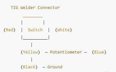
The switch and potentiometer work together to control welding power. When you press the pedal:
- The microswitch activates, telling the welder to start the arc.
- The potentiometer adjusts the amperage as the pedal is pressed further.
- The ground wire completes the circuit, ensuring proper function.
Some higher-end pedals may have additional wiring for pulse control or extra amperage settings, but the basic principle remains the same.
How to Wire a TIG Welder Foot Pedal
If you’re wiring a new foot pedal or repairing an old one, follow these steps carefully:
Identify the Wires
First, check the foot pedal wiring diagram for your specific welder brand. Some brands may have different color coding. If you don’t have a diagram, use a multimeter to test each wire’s function.
Connect the Microswitch
The microswitch controls the arc start and stop function. It usually has two wires (red and white). These should be connected to the welder’s start/stop circuit.
Wire the Potentiometer
The potentiometer has three terminals:
- One for input voltage (typically 5V or 10V from the welder).
- One for ground.
- One for the output signal (which varies based on pedal position).
Ensure the correct connections to avoid incorrect amperage readings.
Secure the Ground Wire
The ground wire (typically black or green) ensures the circuit works properly. Connect this to the welder’s chassis or designated ground terminal.
Test the Foot Pedal
Before welding, test the pedal by gradually pressing it while measuring voltage output with a multimeter. You should see a smooth increase in voltage as you press down.
Foot Pedal Wiring Issues and Fixes
Even if you wire everything correctly, you might still run into foot pedal issues. Here are some common problems and how to fix them:
| Issue | Possible Cause | Solution |
|---|---|---|
| Pedal not working at all | Loose or disconnected wires | Check connections and resolder any broken wires |
| Arc won’t start | Microswitch failure | Replace the microswitch |
| No amperage control | Potentiometer faulty | Replace the potentiometer |
| Inconsistent amperage | Dirty or corroded connections | Clean the contacts and check for loose wires |
| Pedal stuck at full power | Short circuit in wiring | Inspect for damaged wires and replace if needed |
Can You Build a DIY TIG Welder Foot Pedal?
Yes! If you enjoy DIY projects, you can build your own TIG foot pedal. Here’s what you’ll need:
- A potentiometer (matching your welder’s requirements)
- A microswitch (to start and stop the arc)
- A metal or plastic pedal enclosure
- Wires and connectors
Simply follow the wiring diagram above, and you can create a custom foot pedal for your TIG welder.
Choosing the Right TIG Foot Pedal for Your Welder
If you need to buy a new foot pedal, make sure it’s compatible with your welder brand. Here’s a quick guide:
| Welder Brand | Foot Pedal Compatibility |
|---|---|
| Miller | Uses a 14-pin connector |
| Lincoln | Uses a 6-pin or 14-pin connector |
| Everlast | Uses a 5-pin connector |
| ESAB | Varies by model |
Always check your welder’s manual to confirm the correct foot pedal wiring before purchasing.
Conclusion
Understanding the TIG welder foot pedal wiring diagram is crucial for troubleshooting, repairing, or even building your own foot pedal.
- The foot pedal controls amperage smoothly, making TIG welding more precise and efficient.
- A potentiometer adjusts the current, while a microswitch controls the arc start/stop function.
- Wiring is usually straightforward, with color-coded wires connecting to power, ground, and control circuits.
- If you have wiring issues, check for loose connections, faulty switches, or damaged wires.
With the right wiring setup, your TIG welder foot pedal will work perfectly, giving you better control over your welds.
FAQs
Can I use any foot pedal with my TIG welder?
No, each welder has specific wiring and pin configurations. Always check compatibility before purchasing.
What potentiometer should I use for a DIY foot pedal?
Most TIG welders use a 10K ohm potentiometer, but check your welder’s manual to be sure.
Why is my TIG foot pedal stuck at full power?
This usually happens due to a short circuit in the potentiometer wiring. Inspect and replace if needed.
Can I repair a broken TIG foot pedal myself?
Yes, most issues like loose wires, bad switches, or a faulty potentiometer can be fixed with basic tools.
What is the best foot pedal for a Miller TIG welder?
Miller uses a 14-pin connector, and their factory pedals work best. However, aftermarket options like SSC controls are also great.